


1. Install the driver
First, install it“setup”、“Setup_JLink_V494g”For the driver, the default installation location is fine.

Then install the USB to TTL serial port driver (CP2102 or CH340). The specific download links are as follows:
Cloud drive link:
Extraction code: 8889
Extraction code: 8889
Extraction code: CKES
Computers that have already downloaded the driver can ignore this.
2. Module and ESC wiring connection
- On the electronic throttleWhite and black 2P signal cableThe white (PWM IN) and black (GND) wires are connected to the TX pin and GND pin on the serial module, respectively.
- On the electronic throttleRed and yellow 2P CAN control linesRed (CAN_H) and Yellow (CAN_L) can be inserted directly into the pins corresponding to H and L printed on the CAN control module.
3. Serial Port Module Port Number Setting
After correctly connecting the wire sequence, insert the serial module into the computer's USB port, find the corresponding COM port according to the steps, the host computer software only supports "COM1~COM3”;
Check if the port number is connected correctly by the following method:
After inserting the serial module, click on the computer“Device Manager”, then click on the port to view it. If the port number is not 'COM1~COM3', you can right-click the device of that port numberAttribute", and then click on "Port Settings", click the lower left corner in this interface "AdvancedSelect the option, then change the port number of the serial module "Error (non-COM1~COM3)" to "COM1~COM3" and confirm. Then, simply unplug and replug the serial module.
4. Electric adjustment mode settings
Open the host computer softwareCKEC_UAVCAN_Debugger 1.01-10ms-250820-Added setting success prompt:

Connect the electronic speed controller to the motor phase wires, then after turning on the host computer, select the correspondingCOM port (only supports COM1~COM3), clickportclosetoportopenThen power on the electronic governor, within 1-2 secondsClick on the upper computer monitor“ESCSET”, the motor appears after clicking“♪1”A motor prompt sound, then click again“PWM1-2ms”、“UAVCAN”、“PWM+UAVCAN”Arbitrary control mode, set specifically according to your own needs.
- In PWM 1-2ms mode, only PWM control can be performed;
- In UAVCAN mode, only CAN control can be performed.
- Both can be controlled in PWM UAVCAN mode.
- After clicking the set mode, the motor will also give a beep. The appearance of the beep indicates that the setting is successful.
- PWM 1-2ms mode beep "♪1" once;
- In UAVCAN mode, the beep '♪2' sounds once;
- PWM UAVCAN mode prompt sound '♪123' three continuous tones;
- After setting in PWM mode, you can control it directly without any other operations. The throttle travel range is 1000-2000us.
- Both UAVCAN mode and PWM UAVCAN mode require additional settings, which should be configured according to the following procedure:

5. Baud Rate Settings
- After setting the above mode, if you need to configure the ESCUVACAN or PWM UVACAN modeFor the control settings below, you need to first use the serial module to operate the ESC in the function box under the host computer.Baud Rate Setting(Default 500K, supported settings: 100K, 125K, 200K, 250K, 500K, 1000K); set the baud rate atWithin the 500K selection boxSelect text with the mouse and enter it, then click directly below“set br”;
- Baud Rate SettingPrompt Tone ♪3A sound indicates that the setting was successful;
6. CAN module port number settings, ID, channel settings, and usage
After setting the above baud rate, it needs to be changedCAN Control Module Settings, insert the CAN module into the computer's USB port, and then proceedPort Number Settings(COM1~COM3), the setting method is the same as above for serial port settings and port numbers. After the settings are completed, you can proceed with baud rate, ID, and channel settings.

(The CAN ESC is factory set to PWM UAVCAN mode, baud rate: 500K, ID: 1, channel: 105), subsequent settings can be modified according to your own needs.

ClickportclosetoportopenThe left display boxes on the rear upper computer for speed, temperature, voltage, and current all show '0', then power on the energized controller. After powering on, the motor appears at one-second intervals.Continuous beep '♪3', waiting to set the baud rate;
Set the baud rate toWithin the 500K selection boxUse the mouse to highlight text for input, and click directly below after entering“set br”, baud rate settingPrompt Tone ♪3A sound indicates that the setting is successful, and a prompt box appears to show that the setting is successful.

Then proceedID and channel settings, the settings interface is in the right-side box of the CID (ID and channel are entered in the same box), click after entering the ID“Set id”, ID, channel settingsPrompt Tone ♪3A sound indicates the setting is successful; and it all appears“设置ID成功”The prompt box indicates that the setting was successful. Note to set the ID first, then set the channel;

After the setup is complete, click the red box on the right side of the upper computer ID input field. After clicking, the background turns white, and the continuous alarm sound of the motor disappears, allowing control through the slider area on the right. Subsequently, control can be achieved via a flight controller with CAN protocol.

7. Introduction to the Host Computer Function Module and Other Instructions
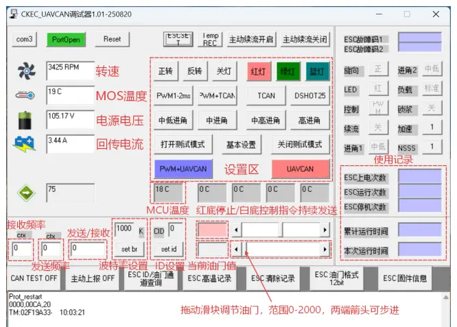
Host computerThe speed display item is factory-set by default to 42PThe calculation can customize the speed parameter based on the actual slot and pole pair numbers of the customer's motor. At this time, the displayed speed corresponds to the actual speed of the motor.
