




PWM Uni- and Bi-directional ESC Setup Guide
1. Install the driver
- First, install it on the computer“setup”For the driver, the default installation location is fine.
Then install the USB to TTL serial driver (CP2102 or CH340). If your computer already has the serial driver installed, you can ignore this. The specific download links are as follows:
Cloud drive link:
Extraction code: 8889
Extraction code: 8889
Extraction code: CKES
2. Module and ESC wiring connection
- On the electronic throttleWhite and black 2P signal cableThe white (PWM IN) and black (GND) wires are connected to the TX pin and GND pin on the serial module, respectively.
- On the electronic throttleRed and yellow 2P CAN control linesRed (CAN_H) and Yellow (CAN_L) can be inserted directly into the pins corresponding to H and L printed on the CAN control module.
3. Serial Port Module Port Number Setting
After correctly connecting the wire sequence, insert the serial module into the computer's USB port, find the corresponding COM port according to the steps, the host computer software only supports "COM1~COM3”;
Check if the port number is connected correctly by the following method:
After inserting the serial module, click on the computer“Device Manager”, then click on the port to view it. If the port number is not 'COM1~COM3', you can right-click the device of that port numberAttribute", and then click on "Port Settings", click the lower left corner in this interface "AdvancedSelect the option, then change the port number of the serial module "Error (non-COM1~COM3)" to "COM1~COM3" and confirm. Then, simply unplug and replug the serial module.
4. Throttle Adjustment Settings
Open the host computer softwareCKESC Information Display 2.85D_260615(1):
After opening, the interface looks like this:
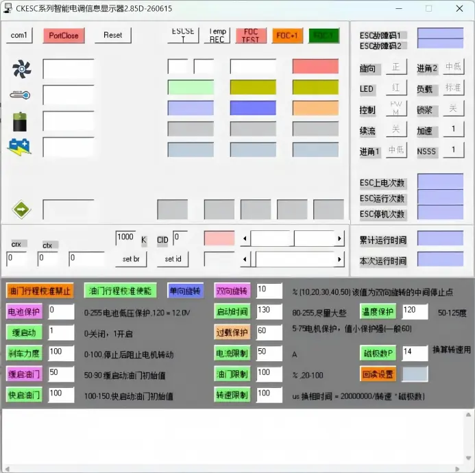
Connect the ESC to the motor phase wires, then after opening the PC software, click to select the corresponding one in the top row.COM Port(Only supports COM1~COM3), clickportclose toportopen, and then click once on "ESCSETEnter the settings interface, and the screen looks like this afterwards, then power on the ESC.1-2S Click again on the ' on the host computer monitorESCSET", after clicking, the motor appears"♪1"A single motor beep indicates that you have successfully entered the settings mode. Once inside, you can set the parameters as needed. After all the parameters are set, if you want to switch back to the debugging mode interface above, you just need to click"The temperature icon on the far left of the host computerThat's all.
5. Introduction to the Electric Adjustment Function
This product is a multi-functional adjustable electronic speed controller, supporting one-way rotation, two-way rotation, motor direction settings, and more, with several features:
Setup is simple: you only need to use the serial module.
Set reminder: When set successfully, the motor will have a prompt sound and a pop-up will show that it was set successfully;
Protection features: low voltage, high voltage, startup, stall, over-temperature, over-current, overload, and loss-of-control protection;
Quick response: the smaller the switch time, the less throttle lag, and the faster the throttle switches between forward and reverse;
Well-equipped features: calibration settings, one-way and two-way settings, low voltage protection settings, brake strength, soft-start switch, overload protection, current limit, throttle limit, speed limit, pole number settings, throttle response speed, and more;
No need to match: ready to use right away, works with any motor, saving you the matching process;
Data feedback: real-time reporting of speed, voltage, current, temperature, and other parameters;
For cars and boats: suitable for multiple scenarios, including drones, cars, boats, and more;
Rotation direction setting: Supports forward and reverse rotation direction setup via the upper computer, no need to manually adjust the phase sequence.
The specific functions are set as follows:
The switch time, throttle response time, and some function block settings are usually preset at the factory according to different application needs. Later on, you only need to tweak a few parameters as needed. For switch time and throttle response, it's recommended to set 2 (200ms) for fixed-wing and 3 (300ms) for other applications.
Switch time1, 2, 3, 4 gears, the smaller the number, the faster it goes (factory default is 3, the smaller the number, the faster it is, but the risk will be a bit higher)
Throttle response:100ms、200ms、300ms, 400ms, the smaller the number, the faster it is (the factory default is set to 300ms, the smaller the number, the faster it goes, but the risk will be a bit higher);
Throttle travel calibration prohibited: Click the button to activate, after clicking the function indicates that the throttle cannot be calibrated;
Throttle Travel Calibration Enable: Click the button to activate it, and after clicking, it means the function can calibrate the throttle;
One-way rotation: Click the button to activate it. After clicking, the function means the motor can only rotate in one direction;
Bidirectional rotation: Click the button to activate it. After clicking, the function indicates that the motor can rotate in both directions;
(Note: The numbers in the white box on the right need to be filled in by yourself. After filling them in, click the settings box on the left to take effect. This number represents the middle stop position for bidirectional rotation. For example, setting the throttle to 40 means that a throttle of 1000-1400 will rotate in reverse at 40% throttle, while 1400-2000 will rotate forward at 100% throttle.)50 different from the others, indicatesBoth forward and reverse at 100% throttle);
Battery protectionDefault setting is 0, no low voltage protection, maximum set voltage is 25.5V, can be set according to needs;
Start time:You can set it within the 80-255 range; the higher the value, the safer it is, but the startup time will be slower (factory default is 130).
Temperature protectionThe range can be set from 50 to 125, with the factory setting at 120℃.
Soft start1 is on, 0 is off. Turning it off can speed up startup, but it also comes with some risk.
Overload protectionRange 5-75, the smaller the value, the faster the protection, faster than current limiting (factory setting is 60, can be adjusted later based on actual needs);
Brake force0-100, the higher the number, the stronger the braking force. The factory setting is 100;
Current LimitGenerally, the product should not exceed the maximum power of this ESC. You can set the current limit according to your needs (factory setting is 50, and you can adjust it later based on actual requirements).
Number of poles P:For converting rotational speed, you need to fill in the number of poles of your own motor. Once filled in, it will show the actual speed corresponding to the changed number of poles.
Ease onto the throttle: 50-90 initial value for slow throttle start, indicates the minimum throttle point when slow start mode is on, default is 50. The higher the number, the more throttle applied at start;
Throttle limit20-100%, with 100 meaning no limit. The smaller the number, the more restrictions. In the ESC's PC debugging software, the maximum throttle in the box is 1500, which corresponds to an actual throttle of 2000. You can calculate and fill in the throttle according to your actual needs.
Step on the gas100-150 Quick-start throttle initial value, indicating the minimum throttle point when the soft start is off. The default is 100. The higher the number, the higher the starting throttle and the faster the response, but the risk will also be a bit higher.
Speed limitUnit is us, default is 100. The commutation time in us = 20000000 / (speed × number of poles), you can fill in based on the maximum speed point you actually need.
Playback SettingsAfter connecting the feedback line, clicking the read-back setting box allows you to read back the parameters set last time;
Just click the corresponding settings box when setting it up, and if successful, it will show like this:Settings saved successfullyThe pop-up box: ESCs without a telemetry wire won’t show this box when you click read, but you can tell if the settings worked by the motor beep during setup.
6. Introduction to Other Feature Settings
Advanced Settings: (Usually, there's no need to set it up., it may only be needed for special power sources. This feature involves power compatibility, so it is not recommended for general users to change it, and this feature setting can be ignored);
Corner Entry Settings Instructions:
- Low angleAt low to medium throttleForce efficiencywill be higher,Angle of AttackFocus on maximizingTension, and improve compatibility;
- [Factory Default Settings]: Basic Settings (High Entry Angle)+ Advanced settings (medium approach angle), improve compatibility;
- [Recommended Other Settings]: Basic Settings (Medium Entry Angle)+ Advanced settings (medium-low entry angle), improve power efficiency;
On the electronic throttleWhite and black 2P signal wire:White - PWM IN、Black - GND Connect separately to the serial module TX pin、GND pinConnected.
Choose the corresponding one COM port (only supports COM1~COM3), click portclose to portopen Then power on the electronic governor, 1-2S Click inside on the host computer monitor "ESCSET", after clicking, the motor appears"♪1A motor alert sound, and then at "Basic SettingsClick on the basic angle settings in the settings bar abovemedium-low approach angle、Intermediate angle、medium-high approach angle、Angle of AttackSet it according to your own needs. After clicking, the motor will give a prompt sound. If you hear the prompt sound, it means the setting was successful.
Basic SettingsCorner entry sound setting:
- medium-low approach anglebeep♪1"One sound;
- Intermediate anglebeep♪2"One sound;
- medium-high approach anglebeep♪3"One sound;
- Angle of Attackbeep“♪4"One sound;
After finishing the basic settings, click on Basic Settings to go to the advanced settings. The interface looks like this:
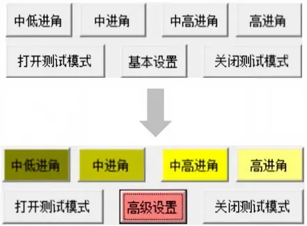
Advanced SettingsCorner entry sound setting:
- medium-low approach anglebeep♪12"One sound;
- Intermediate anglebeep♪32"One sound;
- medium-high approach anglebeep♪42"One sound;
- Angle of Attackbeep♪52"One sound;
Entry angle settings definition:
Low angleAt low to medium throttleForce efficiencywill be higher,Angle of AttackFocus on maximizingTension, and enhanceCompatibility;
[Factory Default Settings]: Basic Settings (High Entry Angle)+ Advanced settings (medium approach angle), improve compatibility;
[Recommended Other Settings]: Basic Settings (Medium Entry Angle)+ Advanced settings (medium-low entry angle), improve power efficiency;
Setting recommendations for different applications:
For multirotor applications that require thrust efficiency, you can set it to low pitch mode.
For applications like [fixed-wing, VTOL] that need consistent response and high safety, it's recommended to stick with the default settings to improve compatibility and safety.
Important Notice:
When switching from a high approach angle to a low approach angle, there is a risk of parameter mismatch; please proceed with caution.
When switching from a low approach angle to a high approach angle, the motor power will increase accordingly. It is essential to ensure the motor operates within its safe power range to prevent overload.
Forward and reverse rotation direction setting:
- ESC white-black 2P signal wire:White - PWM IN、Black - GND Connect them separately to the TX and GND on the USB to TTL serial module, and connect the ESC to the motor wires.
Open the above PC software and select the corresponding one COM port (only supports COM1~COM3), clickportclose to portopen Then, click once on "ESCSET"Enter the settings interface and power on the ESC,1-2S Click inside on the host computer monitor "ESCSET", after clicking, the motor appears"♪1"A motor beep, then click again "Forward/Reverse", after clicking, the motor will also have a beep. The beep indicates the setting is successful, and forward rotation will beep."♪123"Three beeps, reverse alert sound"♪321‘Third tone;
Once set up, it can be used normally without manually switching the phase wiring sequence.
7. Things to Note
This product comes with an adjustable brake force feature. When the brake force is set to 100, the braking is very strong. If you switch back and forth too quickly, the voltage and current may spike. Make sure the wiring is intact and the power supply is stable when using it, otherwise it could damage the device. You can choose to turn on or off the brake mode based on your needs.